Product Description
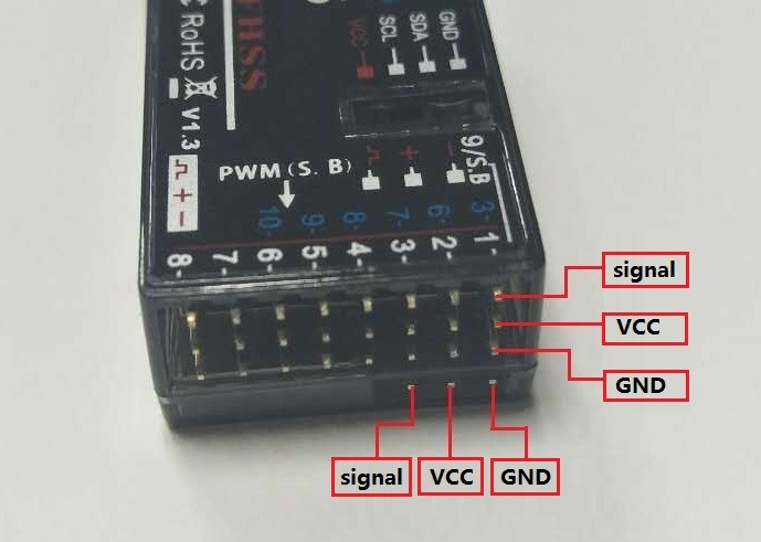
R9DS, with 2.4G DSSS&FHSS technology that operate side by side to reduce signal interference, is a 10-channel receiver that outputs SBUS and PWM signals synchronously. It is compatible with RadioLink transmitters AT9, AT9S, AT9S PRO, AT10 and AT10II.
Two signal working modes:
1. PWM signal output working mode:Receiver indicator is RED with all 9 channels output PWM signal.


(2) S-BUS&PWM signal output working mode: Receiver indicator is Blue(Purple) with 10 channels output in total and synchronously output SBUS and PWM signal.
Ch9 outputs SBUS signal while Ch3 marked in BLUE outputs PWM signal and helicopter is compatible. When Ch6 to Ch10 output PWM signal, there are 10 channels in total.

Signal working modes switch:
Short press the binding button twice within 1 second to switch the S-BUS&PWM signal to PWM signal. When the Red indicator is on, signal output is PWM of totally 9 channels. When the Blue/Purple led is on, signal output is SBUS&PWM of 10 channels.
Binding
1. Put the transmitter and the receiver close to each other within 50 centimeters.
2. Power on the transmitter and R9DS. The RED led on R9DS will start flashing slowly.
3. Switch on the transmitter and it will automatically bind to the closest receiver.
4. There is a black binding button on the side of receiver. Press the button for more than 1 second and release, the RED led will flash quickly, meaning binding process is ongoing.
5. When the RED led stops flashing and is always on, binding is complete.
6. Verify servos connected with the receiver can be operated by the transmitter.
Note Once upgraded with the latest firmware, the channel quantity of the transmitter(AT9/AT9S/AT10/AT10II) needs to be set as 10 to work with R9DS, the 10 channel receiver.
Press Mode button to enter BASIC MENU => Rotate the dial to select SYSTEM and Enter => Set CH-SELECT as 10CH.
Note of Receiver Usage
1. Keep antenna as straight as possible to maximize the control range.
2. Big models may contain metal parts that influence signal emission. In this case, antennas should be positioned at both sides of the model to ensure the best signal status in all circumstances.
3. Antennas should be kept away from metal conductor and carbon fiber at least half inch away and no over bending.
4. Keep antennas away from motor, ESC or other possible interference sources.
5. Sponge or foam material is advised to use to prevent vibration when installing receiver.
6. Receiver contains some electronic components of high-precision. Be careful to avoid strong vibration and high temperature.
7. Special vibration-proof material for RC like foam or rubber cloth is used to pack to protect receiver. Keeping the receiver in a well sealed plastic bag can avoid humidity and dust, which would possibly make the receiver out of control.
When all the above steps are complete, please turn off the transmitter and repower on to test if the receiver is correctly connected with it.
Technical Parameters
Channels Qty: 9 channels for PWM signal output; 10 channels for SBUS&PWM signal output.
Operating Voltage: 4.8-10V
Operating Current: 38-45mA(input voltage: 5V)
Size: 43*24*15 MM (1.69"*0.94"*0.59")
Weight: 14g (0.49oz)
Section Precision: 4096, 0.25us per section
Control distance: 3.4KM(2.11Miles) in the air (Maximum range tested in unobstructed areas free of interference and may vary depending on local regulations).
Compatible with extended telemetry module PRM-01 and PRM-03
 NZD
NZD
 USD
USD
 EURO
EURO
 GBP
GBP
 HKD
HKD
 AUD
AUD
 CAD
CAD
 SGD
SGD
 CHF
CHF


